When you click on links to various merchants on this site and make a purchase, this can result in this site earning a commission. Affiliate programs and affiliations include, but are not limited to, the eBay Partner Network.
Measuring across the pins for the (removed) fuse will not produce a voltage reading unless there is a ground on the other side. You have to measure from the hot side of the fuse to a chassis ground (or replace the fuse and measure from the downstream side of the fuse to a chassis ground). Just measure at the relay pins, to a chassis ground. That's all that matters.
If you were measuring across the (removed) fuse pins, and turning the key to "on" caused the meter to read 12 volts, something supplied a ground. Need to look at "Fuse Block Details Cell 11" to see what might make that happen. Because there is no ground possible at the relay unless the PCM turns on the AIR pump by supplying the ground.
I'll look through the electrical section of the factory service manual.
Here are all the tests I have done
1. Across the back of the fuse key on/off - voltage only when key on
2. From the supply side to ground (fuse in) - voltage only when key on
3. From the supply side to ground (fuse out) - voltage only when key on
4. From the device side to ground (fuse out) - no voltage
With the diagram, I would expect to see voltage on the supply side of the fuse at all times. I wouldn't expect it to impact this test, but the Torqhead PCM is not compatible with AIR, EGR or EVAP.
If you were measuring across the (removed) fuse pins, and turning the key to "on" caused the meter to read 12 volts, something supplied a ground. Need to look at "Fuse Block Details Cell 11" to see what might make that happen. Because there is no ground possible at the relay unless the PCM turns on the AIR pump by supplying the ground.
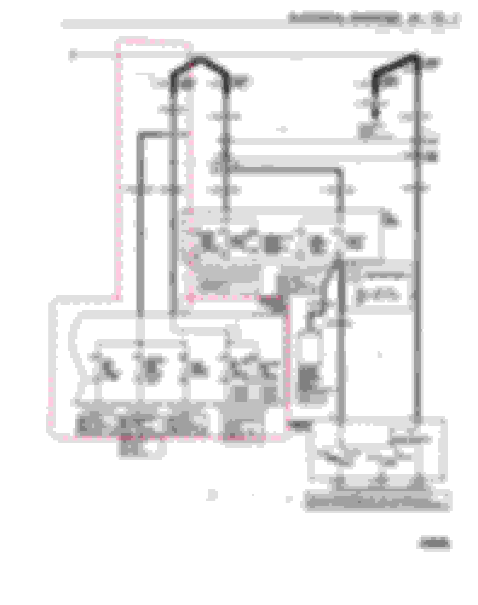
Fred, I think what you're reading in this case is a voltage drop or difference in potentials across the fuse holders. The load side of the fuse holder should have a path to ground through any device powered by that fuse. This photo below from the service manual shows an example of what I'm trying to say. Notice one of the meter leads is connected to a positive potential and the other has a negative potential from the coil of the solenoid in the circuit.
I'm not reading any thing, Drew is doing the measuring. I think you are confirming what I told Drew - the ground could have come from another device on the circuit.
What I was indicating was that when the key was turned to “on”, the ground came from somewhere other than the AIR pump circuit, unless the PCM closes the ground circuit for the AIR pump when the engine is not started - I've never observed that. There are other devices supplied from fuse 7 in the under hood box, including the control side of the three fan relays. I wanted to look at the details of Cell 11. My downloaded copy of the 96 manual (I have always assumed 96 and 97 are similar), has the power side distribution for fuse 7, but the page referenced for the device side (8A-21-3 if I recall correctly) is missing from my copy.
On the 96-97 models, is it possible for the fans to run with the key in the “on” position, but the engine not running?
I'm not reading any thing, Drew is doing the measuring. I think you are confirming what I told Drew - the ground could have come from another device on the circuit.
Poor choice of words on my part, I just meant the 12V reading given. After reading your response again, I would agree, we are saying the same thing. As you mentioned, the ground for the Air Pump relay coil comes from the PCM. I've been unable to find what conditions are required for the PCM to close the contact that provides the ground to the relay coil. I have found that the Air Pump is only suppose to run for a 240 seconds time span, but the manuals don't specify if that period starts at key-on or after the engine starts.
Originally Posted by Injuneer
On the 96-97 models, is it possible for the fans to run with the key in the “on” position, but the engine not running?
I would say yes if the engine temps were above the operating levels used by the PCM to energize them, but that seems to not be factor here. Also not sure if the AC compressor clutch was energized, could that cause the cooling fan relays to energize?
Just when I think I have my mind wrapped around the electrical...
I would think with the air pump fuse pulled, the supply side connected to ground would be hot, regardless of the key position based on the electrical diagram, but I am getting nothing key off.
It seems to me that it would be safer to just rewire the air pump relay manually like this since I would not want the pump to run key off:
1. Remove air pump fuse
2. Tap on ignition device side and connect to air pump relay 86
3. Run a new power feed to the red + power terminal near the battery to air pump relay 87
4. Run from air pump relay 30 to an open supply position in the fuse box
5. Run from the device side of step 4 to the power of the EWP
6. Run a new ground from 85 to the chassis ground below the ABS pump
Does this seem right?
Drew, sometimes people get confused by the fuse block terminals locations because the block has been turned over on it's back. In the drawing I marked up below, the term numbers will match up to how the block was wired from the factory. If you do not want to use the original 12V source, you should be able to rewire the relay socket to a different power source by removing the existing wires on terminals E1 and E5 with the circuit you want to use. Just make sure you isolate the wires you take off so they won't short out.The terminal numbers I used match the drawing you posted above. I don't have a relay here close to cross reference the relay pin numbers you give. I don't think this should effect your cooling fan relays operating as they have in the past.
Something just crossed my mind, if you rewire the relay socket with a new relay coil ground to the chassis, how do you plan on controlling the relay? It will always be energized and run the battery down if you don't have a switching means between the chassis ground and the relay coil.
That is what is frying my brain. The outside of the air pump fuse is not showing voltage unless the key is on. For the switched power, I planed on tapping the ignition wire to activate the relay.
Does it matter what side of of the relay in the power feed the fuse is on? I could use the original power feed off the air pump fuse to the relay, then run the pump feed from the other side of the relay to the pump.
Before I start changing any wiring, the fuse for the air pump is already switched power with a 12 gauge feed wire powering the air pump, abs and fan/accy. Since there is already a fused, switched connection, that already had a 20 amp load, I should just need to wire the pump to the cold side of the air pump fuse, right?
Has the wiring to the air pump been modified? If not the pump should be fed through the #7 fuse first, then supply the relay coil and the relay contact it's 12V power. The factory wiring should have no switch in the 12V+ wire to the fuse or relay. The ground supply is switch by the PCM to activate the coil of the relay.
Originally Posted by DrewHMS97SS
I thought it was strange that this fuse still had power with the air pump relay removed.
That's because the fuse is before the air pump relay. Terminal L7 of the #7 fuse provides 12V to terminals E1 and E5 of the relay
That is what is frying my brain. The outside of the air pump fuse is not showing voltage unless the key is on. For the switched power, I planed on tapping the ignition wire to activate the relay.
Does it matter what side of of the relay in the power feed the fuse is on? I could use the original power feed off the air pump fuse to the relay, then run the pump feed from the other side of the relay to the pump.
How are you checking for voltage at the left side fuse holder? Are you placing the leads of your meter between the two fuse holders or one lead to the left fuse holder and the other to a chassis ground?
Fuse #7 is fed straight from Fusible Link K so there should be no switches to control it unless the wiring has been modified or splice S163 has come apart. Do you have 12V on the left side fuse holders of fuses #6 and #8? They are fed by the same fusible link as #7. Have you tried using the negative post of battery for a ground source for your meter to make sure you haven't lost a ground connection?
Thanks. I’m not sure what I am doing differently today, but I tested from the supply side to the negative side of the battery and had 12v with the key off. I tested again to the radiator support ground and still had 12v.
The only mystery now is what I was doing over the weekend.
With that part solved, does it matter which side of the relay the fuse is on?
Thanks. I’m not sure what I am doing differently today, but I tested from the supply side to the negative side of the battery and had 12v with the key off. I tested again to the radiator support ground and still had 12v.
It looks like you painted the side walls of the engine compartment. Did you use bed liner like you used on the floorboards? If so, you might want to check that the ground cables are making good contact with the body.
Originally Posted by DrewHMS97SS
With that part solved, does it matter which side of the relay the fuse is on?
The fuse is for circuit overload protection. Normally I would say the fuse should be before the air pump relay in order to protect both the relay coil and its contact for a direct short or overcurrent draw.
Awesome, before the relay is actually the easier of the two in routing.
The engine well was just painted, the bed liner stops in the transmission tunnel. Ground seems good, I resistance tested each ground with the negative side of the battery and am seeing 0 ohm.

 04-07-2020, 01:01 PM