When you click on links to various merchants on this site and make a purchase, this can result in this site earning a commission. Affiliate programs and affiliations include, but are not limited to, the eBay Partner Network.
Doesn't the PCM kill the air pump after the first few minutes of cold startup??
The 411 you & peterpar are discussing is way above my pay grade but IIRC the air pump only runs for the first few minutes after a cold start so IDK if that will affect how you harvest that circuit/fuse/relay for your EWP.
Its been 20+ years since I wired up my EWP but I did it as a standalone outboard circuit with a relay/fuse. Will be cool if you can harvest your air pump circuit for EWP
Correct, the AIR pump has to shut off before the PCM switches to closed loop. Typical timeout to enter closed loop is 206 seconds.
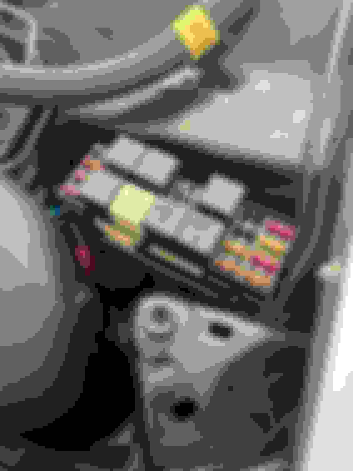
Now that I have a clear understanding of the air pump fuse, I just need to rewire the relay. The pins are a PITA to get out of the fuse box, but I found that using my smallest allen wrenches in the top and bottom of the fuse pins allowed the connection to be popped out.
The connectors in the box appear to be called GM Con III series terminals. I ordered a 25 pack, but it does not look like they will be here until the end of the month.
The GM relay seems to be the same as the generic on that I bought:
When pins 85/86 are energized, pins 30 and 87 are connected.
The plan then is to use the existing feed at the air pump fuse, where I will connect the cold side of the fuse to pin 87 on the air pump relay. From there, pin 30 will be a new wire running to the power side of the EWP. To turn on the air pump relay, I will tap the ignition fuse to pin 86 on the relay. Pin 85 will be a new wire down to the strut town ground.
I am debating currently if I want to run the power feed and ground across near the alternator or loop all the way with the PCM wires. I think the PCM location is cleaner and goes with the rest of the car wiring, but it's another location crossing header heat. I am leaning towards the alternator route since the battery charging cable already takes that route.
The plan then is to use the existing feed at the air pump fuse, where I will connect the cold side of the fuse to pin 87 on the air pump relay. From there, pin 30 will be a new wire running to the power side of the EWP. To turn on the air pump relay, I will tap the ignition fuse to pin 86 on the relay. Pin 85 will be a new wire down to the strut town ground.
Drew, it shouldn't make a difference for how you are using the relay, but generally term #30 would be used for the 12V power supply to the relay contacts and term #87 would be going to the device the relay is controlling. The reason for this is some relays have both a NO and NC contact and term #30 is common to both term #87 and #87A (if used). If you were have the contact power supply go #87, there would no electrical path possible through the relay contacts because the #87 and #87A terms have no way of connecting to each other. In electrician terms, terminal #30 is called the contact common because it can supply power to both sets of contacts individually depending on if the relay is energized or not.
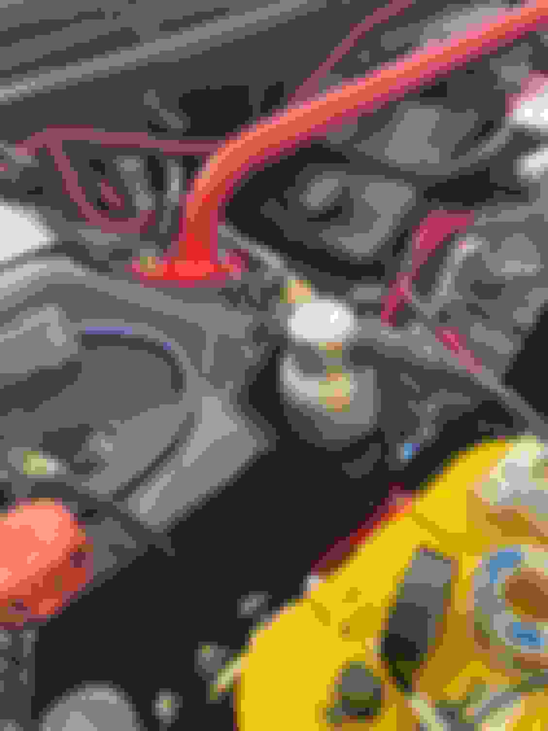
I finally got back after it yesterday and have the pump all wired up. The process was not too bad, where the worst part of the process was getting the pins out of the fuse box. I bought a cheap set of pin removal tools from Amazon, which helped with the fuse connectors, but not the relay. To get the relay pings out, I had to used the smallest allen wrench I had because the ping removal tools were too thin. We have talked about the wiring to death, so I won't relapse that side of it. For the switched based power, I pulled from the ignition fuse. Since I had bought a pack of connectors for the fuse box, I cut the pin off the pink wire, then crimped a new connector to the pink wire and a jumper going to the relay. All of the original relay cables were cut with a little bit of stagger, then tapped up to prevent anything touching. The last thing I need to do is break out the label maker and update the fuse box pics.
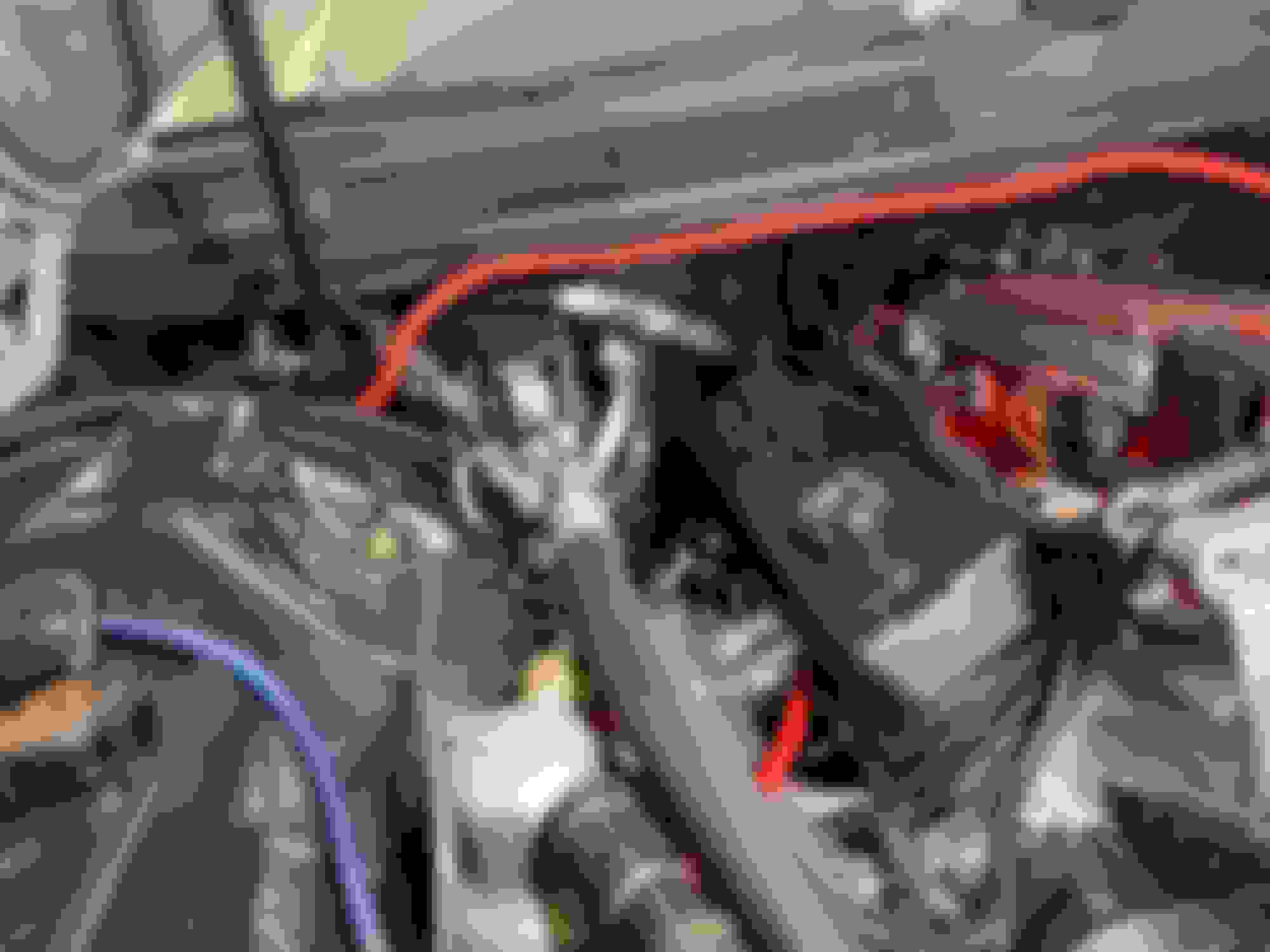
Post install, still looks stock... Power feed going to the pump. Pump ground, and cables crossing over below the alternator. I found some really cool heat shrink crimp connectors, I was surprised with how tight they got on the wire.
I also go the steering shaft back in and was surprised how well it cleared the headers.
Last edited by DrewHMS97SS; 04-20-2020 at 08:51 AM.
Reason: Addition
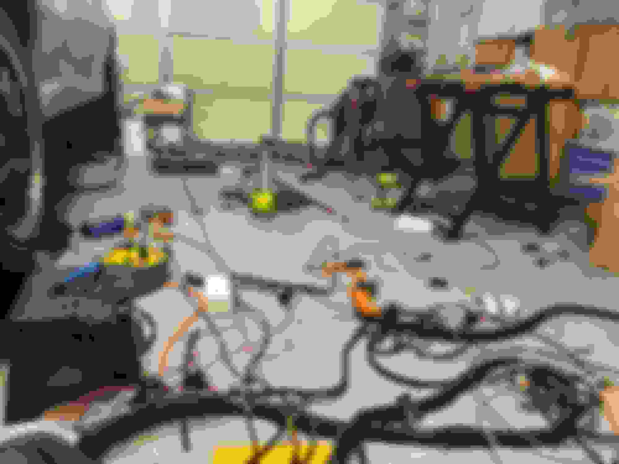
I am back after it again. I have shifted gears a bit and have decided to convert to a Holley Terminator X and digital dash setup after looking at cost and process of tuning via HP Tuners. I wish I had decided this earlier as I could have saved a fair amount of money on the 24x conversion kit. I just pulled back the harness and am in the process of separating out the wires from the engine bay that enter into the cabin so I can remove the old wiring. It is a bit overwhelming, but I will get through it.
In prep for the terminator, I pulled the stock instrument cluster and had a Dremel field day:
This was just a rough cut with the bezel sitting in the original bracket that held the pcb and lights.
with a bit more time, I was able to cut the clear plastic off, and fit the Holley trim on the inside line of the bracket. I wont lie, it took a lot of time, but I am happy with the result.
Looks good Drew, I'll be starting on my 97 SS when the weather warms up I'm going to clean the engine compartment, under carriage and frame then use POR-15 then weld in my dual SFCs before I install my engine/trans/S60 with the tubular K-frame and A-Arms yada yada yada.
Looks good Drew, I'll be starting on my 97 SS when the weather warms up I'm going to clean the engine compartment, under carriage and frame then use POR-15 then weld in my dual SFCs before I install my engine/trans/S60 with the tubular K-frame and A-Arms yada yada yada.
Nice, subframe connectors made a huge difference in my car. The suspension stuff was more about making extra room, but it made a difference too!
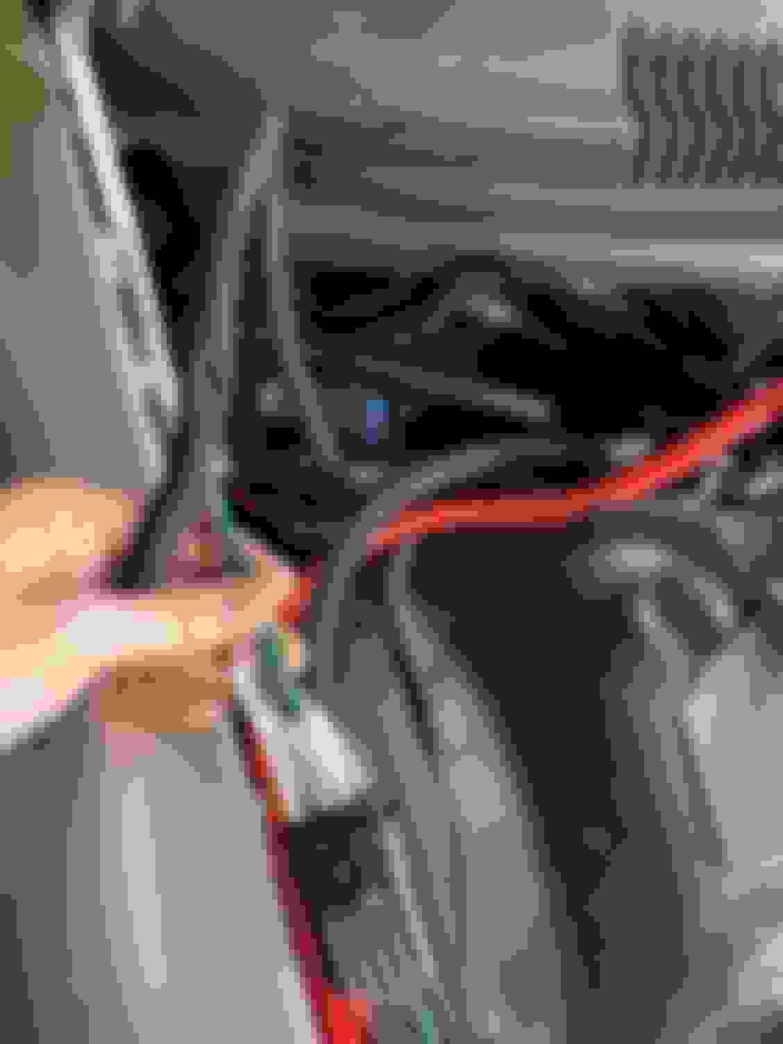
I have been going over the harness to make things line up better for the LT versus the LS. It seemed so easy, but has taken me a couple of days. The main issues I battled were related to changes of how the Torqhead system plugs in versus normal LS positioning. With Torqhead, the coil packs plug in at the rear of the engine, where the Holley harness was designed to plug in about half way up valve covers on either side. It also amazed me how much the few loose battery and ground wires angered me as I flipped the harness around trying to put connectors where I wanted them.
The most notable difference from where the LS harness is designed to plug in to the LT mod is that the cam and crank sensors. For the LS, the cam sensor is at the back of the block near the oil pressure sensor, and the crank sensor is at the bottom rear passenger side, at about the same level as the LT1 knock sensor. I looked at just extending the harness, but after looking at how the shielding was integrated into the wires, I ended up replacing the full length of cable. The Holley plugs for the ECU and accessories made some of the work easier. I ordered a 25' length of the shield cable Holley uses, then measured out two new cables for each sensor. I had also already bought a set of Holley pins to add to the pro dash, so this wasn't much of a stretch. I then cut the existing cables heat shrink to verify the cables I made were wired exactly the same. Both sensor shared power and ground, then fed unique signal locations. The ground wires also connected to the shield ground. Once all the terminations were completed, I had to un-tape the full length of harness to remove the old cables. I worked forwards by removing each pin, then replacing it in the harness plug to ensure I had the right pin in the right place. Once all the pins were removed, I un-taped the harness, pulled the old cables away, then re-taped the new cables in the same place. This is a pick of the final result. After getting everything together, I found that the Torqhead crank sensor actually had a different plug, and was able to buy a replacement connector, then just swapped the pins.
For the digital dash, I did not want to cut into the factor wiring. I hunted around trying to find the metripack male connector for the dash harness, but came up bust. I ended up de-pinning the connector from the instrument cluster circuit board, then soldering my wiring onto the pins. I really should have bought a solder vacuum for this activity, but I figured it would be the only time I ever used it and bypassed it:
This is the final backside of the pro dash with the connector from the instrument panel. I placed some weather stripping on the back side of the connector to protect the pins from contacting anything and to put a little pressure from the dash to keep it plugged in.
This is the pro dash main harness with all of the additional cable and labels:
And finally the dash installed:
Last edited by DrewHMS97SS; 12-17-2020 at 12:06 PM.
Reason: Updated info and picture order
Here is a snap of the dash turned on with the A-pillar returned to stock (removed the 3 gauge pod since the dash has the flexibility to show all of the info I am looking for:
This is the finished side of the C-200 connectors on the interior side of the Holley harness:
This is the C100 connector with some of the original connections, and the additional wires from the dash, and EWP manual ground swich:
I replaced the breather to the valve cover with silicon tubing, then used some of the braided weave over hose. The old tubing was warn and wasn't making a seal on the TB. Thanks to my friends at FigSpeed for the suggestion on the loom:
From a scrap of extra plastic from the dash, I make a plate to replace the DLC with a USB port that it connected to the Holley CANBUS to USB adapter (this looks off from the photo, but I promise it looks parallel to the floor board in the car):
This shows heat wrap added to the Holley loom where is crosses over to the engine. You can also see the vacuum lines all replaces with hi temp silicon:
Finally the ECU mounting. I cut the top half of the LT1 bracket and mounted the terminator with bolts:
The car fired right up first key turn, but brittle o-rings on the FPR dumped fuel all over the ground. I was able to replace on of the o-rings on the rail side and then changed fittings on the bottom of the FPR to delete the lower o-ring. I bought a 45 degree AN fitting and an Earl's AN to quick disconnect.
The car will run if I keep my foot on the gas a bit, but will not stay running without some throttle. I'm currently trying to figure out if my injector settings are correct and think this is the issue.
Last edited by DrewHMS97SS; 12-17-2020 at 12:21 PM.
From the EWP/fan post, when working with getting the engine up to temperature so Terminator X could start it's learn process, and to set the IAC, I discovered that my fans were not turning on. The the car got up to about 235 before I shut it down, which I am not really happy about, but I think is below a real danger zone.
From investigation of the EWP wiring, the orange wires that were part of the air pump circuit were also tied to the fan relays. I added these back to the EWP circuit and the fans are working again. The Holley software is pretty flexible for how it triggers outputs. You can enable an output based on another output being on and/or a set of parameters. For the EWP, I have it set to to turn on anytime the engine RPM is above 250 RPM. Once my idle is sorted out, I think I will get this up to 500RPM to prevent the pump from coming on while cranking.
On the fan side of things, I have a few items configured:
Low speed fan:
1. If the A/C is on, the low speed fan will always be triggers
or
1. If the engine CTS is above 170 degrees
-Deactivate if CTS is below 162 degrees
High speed fan:
1. If fan speed low is on
and
1. If the engine CTS is above 190
-Deactivate if CTS is below 182
I am thinking once this gets going, I will add a second parameter to the conditions where if speed is above, say 40 MPH, the fans will turn off. I think I had seen info about when the fans shut of from the factory, and need to dig in more before making this change.
I ran the car again yesterday and saw consistent temps when idling after low speed fans kicked on at 170. I was attempting to follow the Golen breaking proceedure of keeping the car at 2k for 20 minutes to seat the rings, but the car was hesitating at speed in closed loop with the Terminator X controlling fuel. The base spark map does change advance at 2k, so to make sure everything is safe I have reached out to a tuner to get the tune sorted out (a small price to pay to ensure I don't break it). One it was up to speed the rockers were pretty noisy too, so I know they need adjustment as well.
On todays list:
1. Get an updated tune file
2. Get the engine to temp
3. Re-adjust the rockers
4. Set the IAC
5. Run through the engine break in
While waiting for the tuner, I am going to attempt my hand at dash artwork. I would like to make a dash display that looks similar to the white faced gauges I had, plus the extra items like fuel pressure, MAP, etc. This will likely turn out bust as art is not a talent, but it will be fun at the very least.

 04-08-2020, 04:07 PM