Now what?
#31
Re: Now what?
Here’s a way, from Shoebox to see if Opti signals are reaching the PCM, and being sent to the ICM (white wire in the ICM connector):
4th Gen LT1 F-body Tech Articles
The second part is a check to see if the PCM is providing the correct voltages to the power wire and signal wires. If the Petris Opti has a permanently attached harness (no harness connector), you have to check at the gray connector on the bracket on the passenger side of the intake manifold.
If aIf the voltages from the PCM are OK, then you need to check for the signals from the Opti. That can be done while cranking the engine. Best way requires a small oscilloscope, but can also be done using the AC voltage function on a multimeter.
#32
Re: Now what?
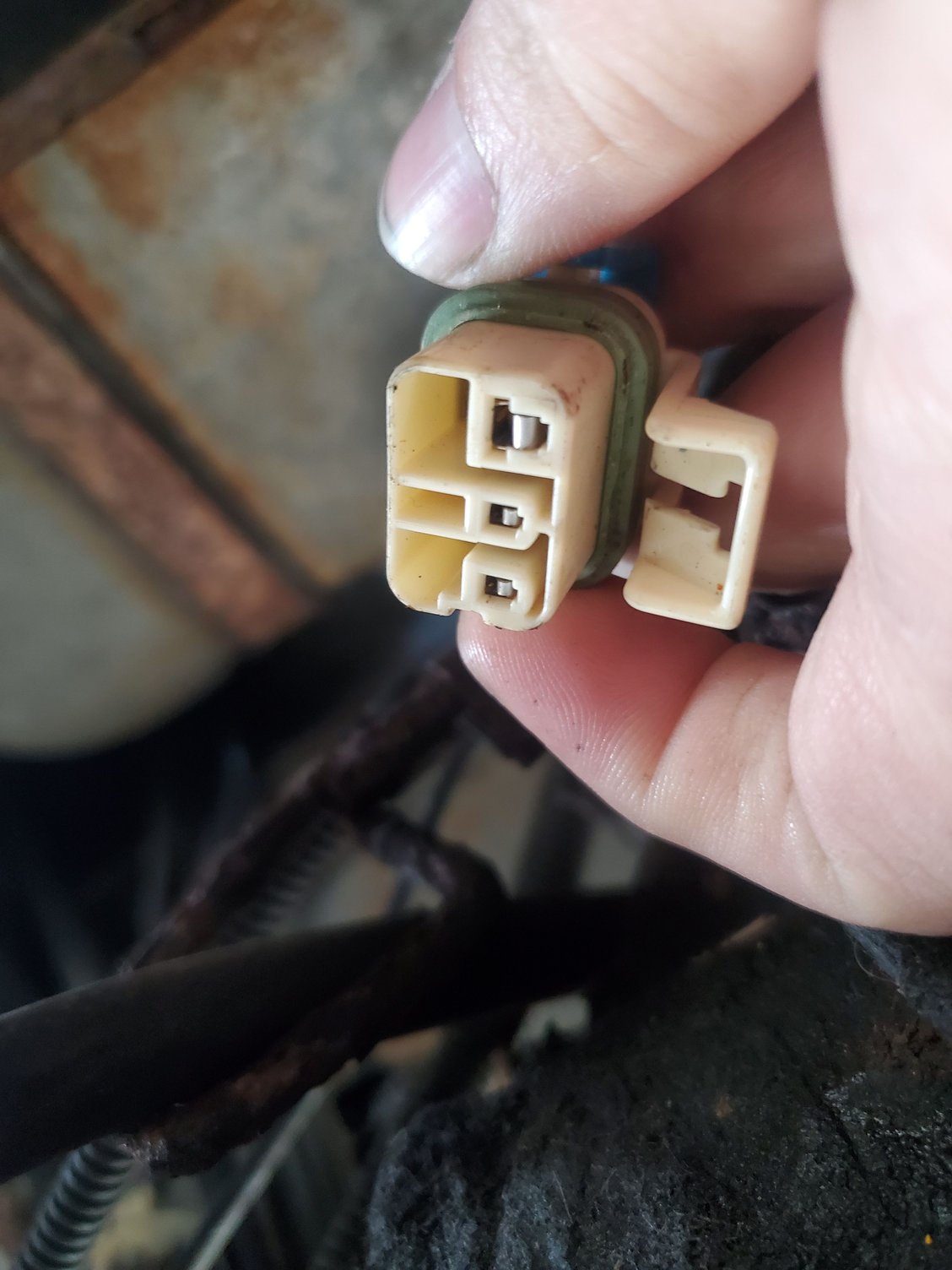
The harness to opti isnt fixed to the opti.
https://petrisenterprises.com/collec...32075760992310
This is the exact kit I installed. The details is what sold me. Ill have to check the voltage when my multimeter gets here tomorrow. I saved that link you sent for testing values. I just wish my obd2 would connect so I can scan for codes. Thanks again (Fred I assume from other threads I've read).
#36
Re: Now what?
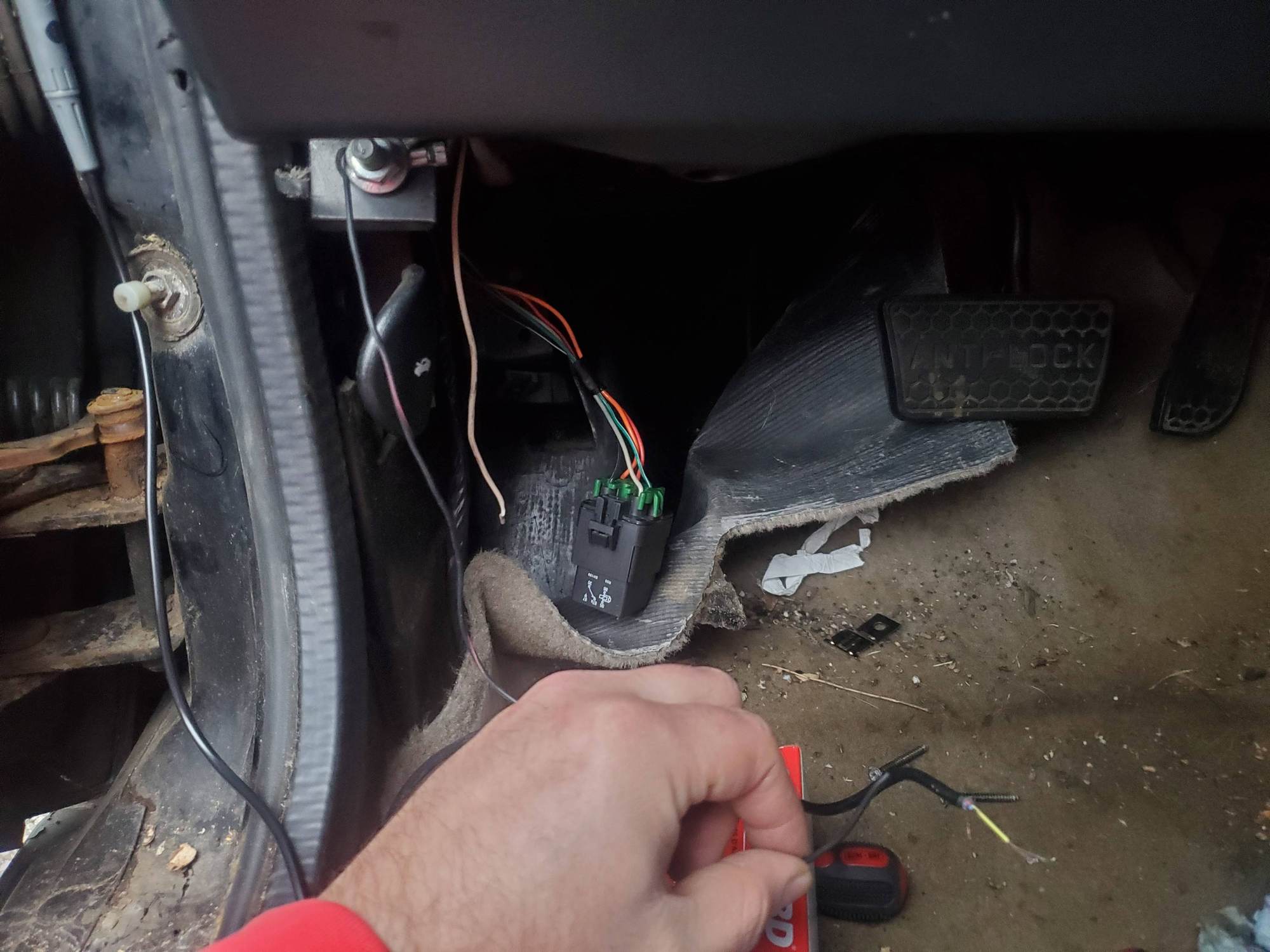
I measured with it grounded to battery key on, I will connect those pins tonight or tomorrow (its cold in ohio). Should be on ac scale correct? Also out of curiosity I checked fuel pump relay and when I got the carpet pulled back I noticed a white wire on the left side checked voltage to see if it was a live or dead wire, i got 12v dc going through it. The owners son before me did have a neon underglow setup that he took off. Maybe its the power wire that fed it? Pic below.
#40
Re: Now what?
All voltages on the Opti connector are DC. You need to measure the A and B voltages using pin D in the connector as the ground. All those wires come from the PCM.
The fuel pump relay wiring is shown in the 1996 factory service manual I linked in post #4. Can be hard to locate. Normally I would access the manual from my laptop PC and provide wire colors and volts, or at least the page #. But I'm not at home right now. I can’t access it until tomorrow around noon time. You can’t reference the diagram for the earlier years, like the 95 diagram on Shoebox because in 96 they switched from a 4-wire relay to a 5-wire.
The fuel pump relay wiring is shown in the 1996 factory service manual I linked in post #4. Can be hard to locate. Normally I would access the manual from my laptop PC and provide wire colors and volts, or at least the page #. But I'm not at home right now. I can’t access it until tomorrow around noon time. You can’t reference the diagram for the earlier years, like the 95 diagram on Shoebox because in 96 they switched from a 4-wire relay to a 5-wire.
#41
Re: Now what?
1996 Factory Service Manual - Page 6E-457. Note, there should also be a schematic in section 8A - Electrical Diagnosis, but it is missing from the downloadable copy.
There are 5 wires attached to the relay:
Pin 87A - red wire - 12 volts from the fuel pump prime connector, only when a power wire is attached to the prime connector
Pin 87 - orange wire - 12 volts from fuse #3 (PCM BAT) in instrument panel block, hot at all times
Pin 86 - black/white wire - ground from chassis ground G110
Pin 30 - gray wire - 12 volts to fuel pump, only when prime connector is powered, or if PCM is supplying 12 volts to relay
Pin 85 - dark green/white wire - 12 volts from the PCM, but only if the PCM detects the "fuel enable" signal (part of VATS) from the BCM, and detects low res pulse signal from the Opti
No white wire.


