
Wiring guru questions
 01-31-2009, 05:11 PM
#1
Registered User
Thread Starter
Join Date: Nov 2006
Location: Houston(clear lake)
Posts: 869
Wiring guru questions
Ok so I am making sure I have everything I need to wire up my led warning lights for my EWP.
I am not good with wires, so I will tell you that up front.
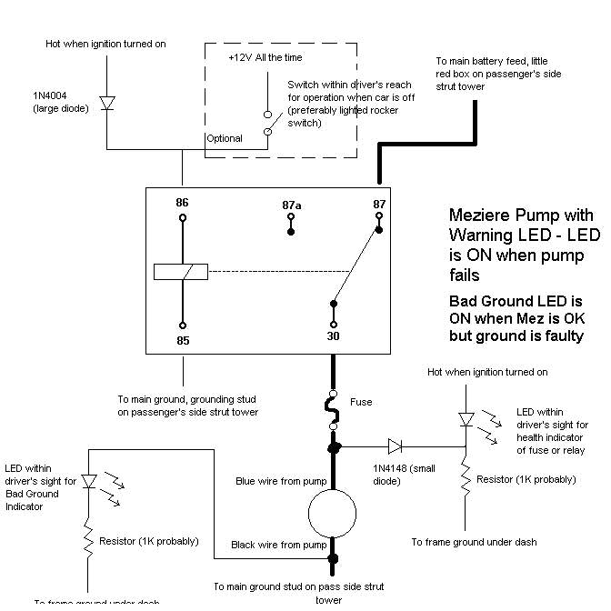
In the attached photo, you install 2 resistors and 1 diode for the warning light side of the circut.
I noticed that the diode is on the hot side(Blue wire) of the pump. What is the purpose of this? I understand a diode allows flow of electricity one way, but why is this necessary? My wild guess is to keep the two positive power sources from mixing.
Ok about the resistors. I am assuming the resistors get wired in to the + side of the power, that is going to the led lights. Right?
On the (Black)ground side of the pump, how does the LED get power other than ground? Is that part missing from the diagram?
I am not good with wires, so I will tell you that up front.
In the attached photo, you install 2 resistors and 1 diode for the warning light side of the circut.
I noticed that the diode is on the hot side(Blue wire) of the pump. What is the purpose of this? I understand a diode allows flow of electricity one way, but why is this necessary? My wild guess is to keep the two positive power sources from mixing.
Ok about the resistors. I am assuming the resistors get wired in to the + side of the power, that is going to the led lights. Right?
On the (Black)ground side of the pump, how does the LED get power other than ground? Is that part missing from the diagram?
 01-31-2009, 10:57 PM
#2
Registered User

Join Date: Nov 2006
Location: Roanoke VA
Posts: 334
[QUOTE=Dave1980;5812767]I noticed that the diode is on the hot side(Blue wire) of the pump. What is the purpose of this? I understand a diode allows flow of electricity one way, but why is this necessary? My wild guess is to keep the two positive power sources from mixing.
The 1N4148 diode prevents current from flowing from the LED and out through the pump. Kind of like an electronic check valve. It does this by putting 12V at the output (cathode) of the LED. 12V at the input (anode), 12V at the cathode and the LED cant turn on. If a relay or wiring fails, the 12V on the cathode goes away and current flows through the LED and 1k resistor.
Ok about the resistors. I am assuming the resistors get wired in to the + side of the power, that is going to the led lights. Right?
For the black wire out of the pump, it doesn't matter where you place the resistor. In front of or behind the LED and the circuit will operate just fine. For the blue wire into the pump, follow the schematic exactly. If you don't, you will short 12V through the 1N4148 and LED to ground releasing diode smoke. This resistor connects between the LED and ground.
On the (Black)ground side of the pump, how does the LED get power other than ground? Is that part missing from the diagram?
The LED gets power from the ground (black) wire out of the pump if the ground disconnects. If you were to connect the blue wire to power, +12V, and measure the the voltage to ground at the black wire, with it disconnected, you would get 12V. When the black wire looses ground it's voltage goes to 12V the pump shuts off and the LED gets juice.
Last edited by ricehammer; 01-31-2009 at 11:07 PM.
02-01-2009, 08:26 AM
#3
Registered User
Thread Starter
Join Date: Nov 2006
Location: Houston(clear lake)
Posts: 869
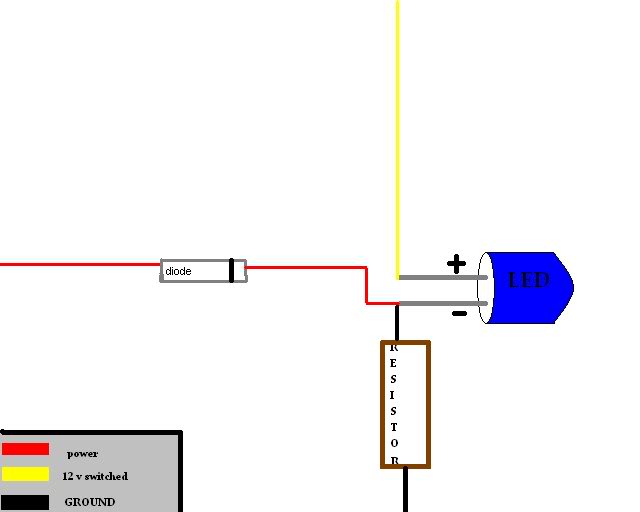
Ricehammer first I would like to thank you for taking the time to explain that. The only thing I am foggy about at this point is where the LED actually gets tied in on the blue wire side of the system. Below I have some really cheesy paintshop pics that I drew with configurations. I am thinking the 3rd one down is the closest to the wiring schematic , but want to be sure so I dont fry the diode . As you can see I have not wired up anything like this before with diodes.
#1

#2
#3

#1
#2
#3
02-01-2009, 08:50 AM
#4
Registered User

Join Date: Jan 2007
Location: Louisville, KY
Posts: 31
Wire it up like image 3 except the yellow wire should not run between the two terminals of the LED. The yellow wire should connect to the top terminal of the LED and the Red and Black wires should go to the bottom terminal.
Remember that Diodes and LED's are polar, which means you MUST wire them in so the negative side faces the lower voltage. On your schematic that is the right side for the Diode, and the bottom for the LED.
The diode will most likely be marked with a strip on the negative side and the LED will most likely have a small minus on the negative terminal.
Hope this helps.
02-01-2009, 09:27 AM
#5
Registered User
Join Date: Aug 2006
Posts: 572
Dave1980:
If you're not using the coolant sensor port on the passenger side head, you might want to put a 3/8 NPT temp "idiot light" switch there and use it to ground a light and a buzzer (Radio Shack sells a cheap ~$3? piezo-electric buzzer) to protect you if the pump were to fail circuit and not take out the fuse. Also, it would warn of overheating if the pump were to begin seizing up and the coolant flow rate dropped but the fuse hadn't blown yet.
If you're not using the coolant sensor port on the passenger side head, you might want to put a 3/8 NPT temp "idiot light" switch there and use it to ground a light and a buzzer (Radio Shack sells a cheap ~$3? piezo-electric buzzer) to protect you if the pump were to fail circuit and not take out the fuse. Also, it would warn of overheating if the pump were to begin seizing up and the coolant flow rate dropped but the fuse hadn't blown yet.
02-01-2009, 10:30 AM
#6
Registered User
Thread Starter
Join Date: Nov 2006
Location: Houston(clear lake)
Posts: 869
Ok so here is the revision, that should be right. I guess I am not good at reading schematics, or I just dont know all of the symbols yet. I would think the led in the schematic would have more detail.
I would like to hook up a buzzer, that would be nice. The port your talking about has nothing in it stock right? Also can you elaborate on where to find the idiot light switches, that are for certain temps?
Dave1980:
If you're not using the coolant sensor port on the passenger side head, you might want to put a 3/8 NPT temp "idiot light" switch there and use it to ground a light and a buzzer (Radio Shack sells a cheap ~$3? piezo-electric buzzer) to protect you if the pump were to fail circuit and not take out the fuse. Also, it would warn of overheating if the pump were to begin seizing up and the coolant flow rate dropped but the fuse hadn't blown yet.
If you're not using the coolant sensor port on the passenger side head, you might want to put a 3/8 NPT temp "idiot light" switch there and use it to ground a light and a buzzer (Radio Shack sells a cheap ~$3? piezo-electric buzzer) to protect you if the pump were to fail circuit and not take out the fuse. Also, it would warn of overheating if the pump were to begin seizing up and the coolant flow rate dropped but the fuse hadn't blown yet.
Last edited by Dave1980; 02-01-2009 at 10:40 AM.
02-01-2009, 11:43 AM
#7
Registered User
Join Date: Aug 2006
Posts: 572
Dave1980:
Stock, the port between cylinders 6 & 8 has a plug in it. It needs an odd size plug tool to remove ... 8mm square I think. I made a tool grinding down an old 3/8 extension a little. The plug is somewhat soft and the GM uses some sort of sealant on it so without a good fitting tool it's easy to start "rounding out" the center. Try Summit or equivalent vendor for temp switches. Make sure it's 3/8" NPT because the older GM switches that mount in the intake manifold H2O crossover are 1/2".
Stock, the port between cylinders 6 & 8 has a plug in it. It needs an odd size plug tool to remove ... 8mm square I think. I made a tool grinding down an old 3/8 extension a little. The plug is somewhat soft and the GM uses some sort of sealant on it so without a good fitting tool it's easy to start "rounding out" the center. Try Summit or equivalent vendor for temp switches. Make sure it's 3/8" NPT because the older GM switches that mount in the intake manifold H2O crossover are 1/2".
Last edited by NJ-LE; 02-01-2009 at 11:46 AM.
02-01-2009, 06:30 PM
#8
Registered User
Join Date: Nov 2006
Location: Roanoke VA
Posts: 334

 . Sorry I misunderstood ya the first time around
  .
02-04-2009, 09:06 PM
.
02-04-2009, 09:06 PM
#9
Registered User

Join Date: Dec 2003
Location: Ottawa, Ontario
Posts: 69
I used the square drive side of a thread tap to remove that plug in the head with a box-end wrench over the square to turn it. Works perfectly and is very hard, just tap it into the plug with a hammer first.
..also installed the buzzer for overheating. Sensor in the head GM part # 14043275.. turns on at 221F or 105C.
..also installed the buzzer for overheating. Sensor in the head GM part # 14043275.. turns on at 221F or 105C.
Last edited by 6SpeedIROC; 02-16-2009 at 02:56 PM. Reason: added sensor #

Thread
Thread Starter
Forum
Replies
Last Post
lbrowne
LT1 Based Engine Tech
25
11-13-2011 04:25 PM
chevroletfreak
LT1 Based Engine Tech
202
07-04-2005 05:00 PM